This is the first article in a two-part series about how Kernel SDK supports cut geometry for planar clipping boundaries.
In addition to generating clipped and section geometry, starting with ODA SDKs version 20.3, the clipping engine in Kernel can generate geometry output for cut geometry:

This geometry output configuration is very similar to section geometry and can be used with it together. Client applications can customize the behavior of cut geometry without limitations, similar to section geometry as described on the ODA blog previously.
Disabling non-sectionable geometry clipping
By default, all geometry that is not marked as sectionable is simply clipped by clipping planes. ODA SDK’s clipping section interface contains a flag that can be used to disable the described behavior and avoid clipping of non-sectionable geometry.

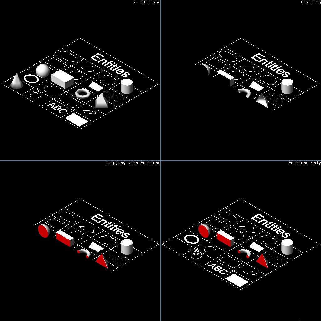
The bottom-right corner illustration shows this flag in use. The bottom-left corner shows standard behavior with enabled clipping of non-sectionable geometry. The behavior of non-sectionable geometry clipping can be controlled by the OdGiSectionGeometryOutput::setNonSectionableGeometryClipping method:
// Set up traits resolver for section geometry
OdGiSectionGeometryOutputPtr pTraitsSets = OdGiSectionGeometryOutput::createObject();
pTraitsSets->setTraitsOverrideFlags(OdGiSubEntityTraitsChangedFlags::kColorChanged | OdGiSubEntityTraitsChangedFlags::kMaterialChanged);
pTraitsSets->traitsOverrides().setColor(1);
pTraitsSets->setSectionToleranceOverride(1.0e-2);
pTraitsSets->setNonSectionableGeometryClipping(false);
// Set up clipping planes
OdGiPlanarClipBoundary::ClipPlaneArray clipPlanes;
clipPlanes.push_back(OdGiPlanarClipBoundary::ClipPlane(m_position, m_normal));
OdGiPlanarClipBoundary bnd; bnd.setClipPlanes(clipPlanes);
bnd.setSectionGeometryOutput(pTraitsSets);
Generating and customizing cut geometry
For this example, we will use the following code from the previous article about section generation:
OdGiClipBoundary emptyBoundary; OdGiPlanarClipBoundary bnd;
::odgiEmptyClipBoundary(emptyBoundary);
// Set up traits resolver for section geometry
OdGiSectionGeometryOutputPtr pTraitsSets = OdGiSectionGeometryOutput::createObject();
pTraitsSets->setTraitsOverrideFlags(OdGiSubEntityTraitsChangedFlags::kColorChanged | OdGiSubEntityTraitsChangedFlags::kMaterialChanged);
pTraitsSets->traitsOverrides().setColor(1);
pTraitsSets->setSectionToleranceOverride(1.0e-2);
// Set up clipping planes
OdGiPlanarClipBoundary::ClipPlaneArray clipPlanes;
clipPlanes.push_back(OdGiPlanarClipBoundary::ClipPlane(OdGePoint3d(202.875, 343.1696, 0.0),
                                                         OdGeVector3d(563.1322 - 247.9639, 172.293 - 147.2914, 0.0)));
clipPlanes.push_back(OdGiPlanarClipBoundary::ClipPlane(OdGePoint3d(247.9639, 147.2914, 0.0),
                                                         OdGeVector3d(202.875 - 247.9639, 343.1696 - 147.2914, 0.0)));
// Set up planar boundary
bnd.setClipPlanes(clipPlanes);
bnd.setSectionGeometryOutput(pTraitsSets);
// Set up viewport clipping
pGsView->setViewport3dClipping(&emptyBoundary, &bnd);
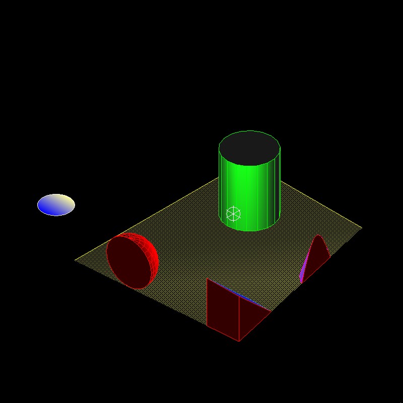
This code applies two clipping planes to an OdGsView (pGsView) object and enables output of section geometry. Section geometry output is customized to output geometry using the red color. Using this code, we can vectorize the following image:
Now we can customize the above code to generate cut geometry instead of sections:

OdGiClipBoundary emptyBoundary; OdGiPlanarClipBoundary bnd;
::odgiEmptyClipBoundary(emptyBoundary);
// Set up traits resolver for cutted geometry
OdGiCuttedGeometryOutputPtr pTraitsSets = OdGiCuttedGeometryOutput::createObject();
pTraitsSets->setTraitsOverrideFlags(OdGiSubEntityTraitsChangedFlags::kColorChanged | OdGiSubEntityTraitsChangedFlags::kMaterialChanged);
pTraitsSets->traitsOverrides().setColor(5);
// Set up clipping planes
OdGiPlanarClipBoundary::ClipPlaneArray clipPlanes;
clipPlanes.push_back(OdGiPlanarClipBoundary::ClipPlane(OdGePoint3d(202.875, 343.1696, 0.0),
                                                         OdGeVector3d(563.1322 - 247.9639, 172.293 - 147.2914, 0.0)));
clipPlanes.push_back(OdGiPlanarClipBoundary::ClipPlane(OdGePoint3d(247.9639, 147.2914, 0.0),
                                                         OdGeVector3d(202.875 - 247.9639, 343.1696 - 147.2914, 0.0)));
// Set up planar boundary
bnd.setClipPlanes(clipPlanes);
bnd.setCuttedGeometryOutput(pTraitsSets);
// Set up viewport clipping
pGsView->setViewport3dClipping(&emptyBoundary, &bnd);
The differences in the code is minimal:
- The OdGiCuttedGeometryOutput class is used instead of the OdGiSectionGeometryOutput class.
- The OdGiPlanarClipBoundary::setCuttedGeometryOutput method is used instead of the OdGiPlanarClipBoundary::setSectionGeometryOutput method to set up the cut geometry output interface.
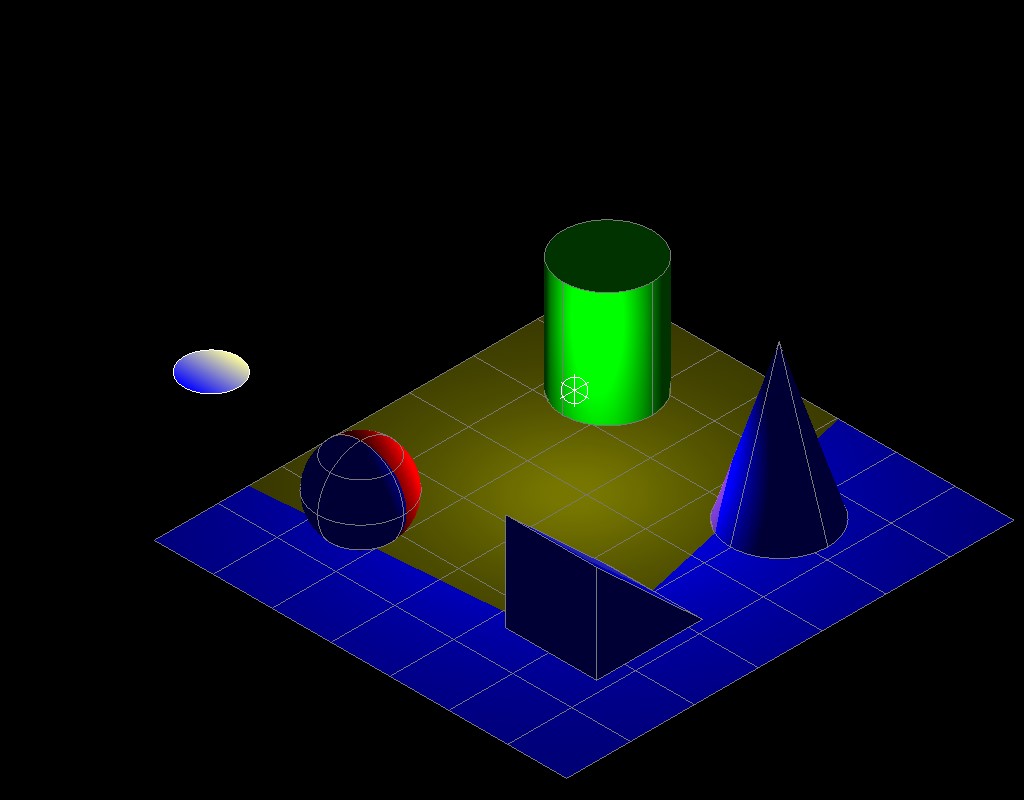
The OdGiCuttedGeometryOutput class is inherited from the same base OdGiClippedGeometryOutput class as the OdGiSectionGeometryOutput class, so methods are almost the same (except some additional flags related to section generation in the OdGiSectionGeometryOutput class). As for section generation, you can override any trait data (we used color and material overrides in this example; instead of the red color for section geometry we used the blue color for cut geometry). Similarly with section geometry, we can override geometry primitives (like the shellProc method, polylineProc method, and so on) to change geometry output behavior, but different from section geometry, the cutting geometry interface can take any kind of geometry primitives, not only shells and polylines.
After the above code executes, we have the following image with generated cutting geometry (blue color) instead of sections:

As for section geometry, the cut geometry output interface contains the OdGiCuttedGeometryOutput::setNonSectionableGeometryClipping method to control the behavior of non-sectionable geometry clipping.
Watch the ODA blog for the next article in this series.


